
Vinci’s Favorite Project!
Seriously, under a lake?
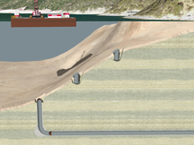
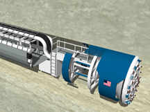
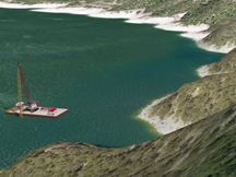
Vinci LLC had produced some large wet infrastructure projects, in the southeast and Midwest, prior to this project. In mid-spring 2009, Vinci is tapped to illustrate the a growing city’s newest water intake and treatment facility. The competition features national and international wet-infrastructure specialists. The work involves drilling two access shafts and starting a hole under a lake from a barge-borne drill. Crews will cap the lake intake as a sort of train that cuts through rock called a tunnel boring machine or TBM bores through from the pump station access shaft to connect to it. The TBM will then bore through to the water plant access shaft, where it will be extracted. Geology is key; Vinci must include the key formations, as a stratum of karst stone must be avoided. A pump station and a water processing plant will be built and link to the city’s water supply system. At first, details of the interview requirements were not available. Someone at a meeting worried, “I don’t know how you will visualize all that’s going on underground plus address geology.”
Fifty out of two thousand
The basis documentation for this project involves a twin-volume preliminary design report, essentially a 2,006-page RFP. Vinci extracts about 50 essential pages, mostly drawings and diagrams, in about 2 hours on the first day of work. Production begins with terrain. This terrain model would prove to be the largest assembled to date by scale-area, covering more than 20 square miles. The USGS DEM is simplified afield of three areas of focus, and enhanced by surveyors’ data provided in the basis documentation. Local existing major and minor improvements are built. The optimization and detailing of terrain requires about 2 levels of work all by itself, and serves as the basis of subsequent work.
Three sites in four weeks
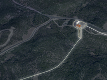
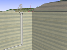
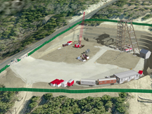
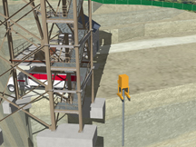
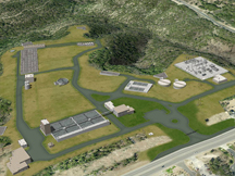
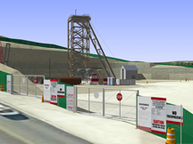
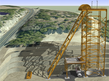
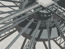
Vinci begins to slay each proposed major improvement based on design development plans and elevations in the basis documentation. Vinci SurePlan™ helps situate these components on their worksites. A curving section along the centerline of the raw water transmission tunnel inverts is produced; geological formation data are applied to the sections. The pump station, designed to “blend in” with the tony homes near the site, is built in a day and a half, complete with internal pumps and the underground shafts to the tunnel system hundreds of feet below. The cutting of the pump station site comes together in one day. The intake site is trimmed out, with a “Moses”-style view of the underwater worksite. Vinci uses 4d underground construction details to view the tunnel work. Vinci begins work on the major improvements of the water processing plant, including clarifiers, gravity thickeners, an electric transformer field, and various service buildings as conveyed by the basis documentation.
As the deadline draws near, the audience organization imposes a limitation on the length of interviewee presentations, so the 4d construction graphics at the water plant are simplified to a scheduling diagram similar to that produced for Vinci Project No. A7B54. The effort is focused on the pump station, intake site, and the tunnels. Vinci builds a headframe based on a description from the client’s consultant, which is modified once and set in place at the pump station. By mid June, an annotated presentation is underway that includes these sites and the tunnel. The scheduling diagram covering the water plant comes together once these segments are delivered. In all, 177 slides were produced, giving the client flexibility to select the views that will make their point as convincingly and succinctly as possible.
The most exciting bore
Vinci Project Number A82A4 stands as the most exhiliarating work Vinci has done as of the time of this page’s writing. The scale of the work and the challenge of producing it represent highlights of Vinci’s portfolio. Making the construction graphics convincing and substantive would prove so successful both here from engagements in the southeast that the winning builder of both projects would contact Vinci for their own work later in 2009. Check out how Vinci’s visualization approaches the appearance of actual images of the work; visit the project website and view actual construction imagery plus additional information on the actual work there.
This page last modified Wednesday 16 November 2011.